Cluster Fixer
214-616-7858
Email: Shannon@clusterfixer.com
![]()
![]()
![]()
![]()
![]()
![]()
Silverado, Sierra, Suburban, Yukon, Tahoe, Avalanche, Escalade
Silverado, Sierra, Suburban, Yukon, Tahoe, Avalanche, Escalade
1. Apply the parking brake to prevent the vehicle
from moving
2. If equipped with and automatic transmission, move the shift lever all the way
down to last gear.
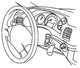
3. Tilt the steering wheel to the full down position
4. Pull gently rearward on the corners of the bezel from the instrument panel
(IP) assembly
5. Remove the bezel
6. After removing the trim plate bezel simply remove the four ¼” screws holding the instrument cluster in place. Pull the cluster out and unplug the single wiring harness connection in the back.
1. Tilt the steering wheel to the full down
position
2. Remove or lower the left closeout/insulator panel
3. Remove the 4 screws from the knee bolster trim panel
4.
Remove the 6 screws retaining the bezel to the instrument panel (Chevrolet).
GMC and Buick version below (4 screws):
5. Remove the bezel from the instrument panel.
(Chevrolet: by tilting it towards the passenger side out of your way, it’s not
necessary to remove the 4x4 or wiper switch.)
6. After moving the trim plate bezel to the right, simply remove the four ¼”
screws holding the instrument cluster in place. Pull the cluster out and unplug
the single wiring harness connection in the back.
1. Remove the knee bolster panel
2. Remove the front floor console trim plate
3. Remove the instrument panel (I/P) accessory trim plate.

4. Remove the 3 screws from the I/P cluster trim
plate at the assist handle
5. Pull out the I/P cluster trim plate in order to release from the retainers.
6. From the back side disconnect the driver
information center (DIC) from the I/P cluster trim plate panel.
7. Loosen the steering column bracket and lower the steering column.
8. Remove the I/P cluster trim plate.
9. After removing the trim plate bezel simply remove the four ¼” screws holding
the instrument cluster in place. Pull the cluster out and unplug the single
wiring harness connection in the back.
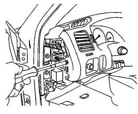
1. Adjust the steering wheel for access.
2. Using a small flat-bladed tool, remove the bezel from the ignition switch
cylinder.
3. Remove the access cover from the left
instrument panel (IP) fuse block.
4. Remove the steering column filler.
5. Open the IP compartment door.
6. Remove the screw from the left side of the IP cluster trim plate.
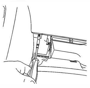
7. Remove the screw from the right side of the IP
cluster trim plate
8. If the vehicle is equipped with a front floor console, position the transaxle
shift control lever to the rear most position.
9. After removing the trim plate bezel simply remove the four ¼” screws holding the instrument cluster in place. Pull the cluster out and unplug the single wiring harness connection in the back.
1. Apply the parking brake
2. Using a small flat-bladed tool, remove the bezel from the ignition switch cylinder.
3. If the vehicle is equipped with a column
shift, position the transaxle shift control indicator to 1. Keep the key in the
ignition switch cylinder.
4. Adjust the steering wheel for access.
5. Remove the steering wheel filler panel
 12
12
6. Remove the instrument panel (I/P) fuse block access hole covers.
7. Remove the screws from the I/P cluster trim
plate.
8. Starting at the right end of the I/P cluster, grasp the trim plate and pull
rearward.
9. Continue working around the I/P cluster trim plate until all of the retainers
are released from the I/P trim pad.
10. Disconnect the electrical connectors from the hazard switch and from the
traction control switch, if equipped.
11. Remove the I/P cluster trim plate.
12. After removing the trim plate bezel simply remove the four ¼” screws holding
the instrument cluster in place. Pull the cluster out and unplug the single
wiring harness connection in the back.
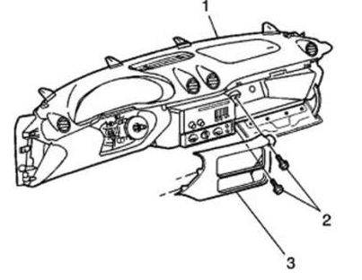
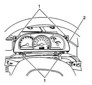
1. Remove the defroster grille screw
2. With flat bladed tool disengage the defroster grille from the instrument
panel (I/P) trim pad.
3. With flat bladed tool disengage the outer trim covers from the I/P carrier.
Pull the cover rearward to disengage the locating tabs from I/P carrier.
4. Open the I/P compartment.
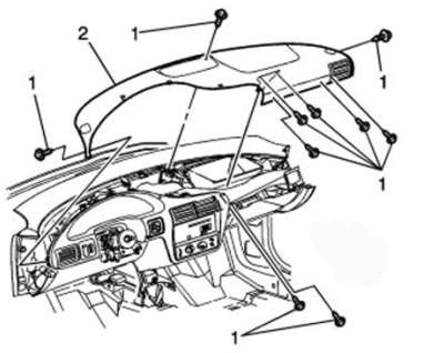
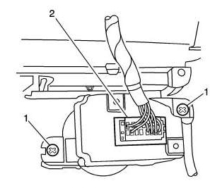
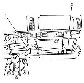
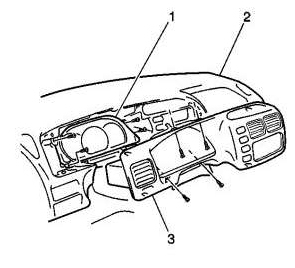
5. Remove the I/P trim pad screws (1)
6. Remove the I/P trim pad (2) from the I/P carrier.
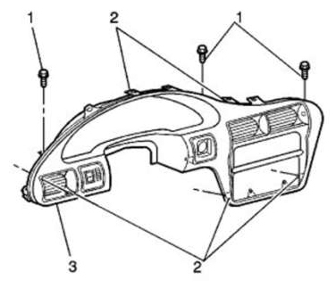
7. Remove the screws (1) from the I/P cluster
trim panel. (3)
8. Remove the I/P cluster trim panel (3). Pull rearward in order to disengage
the retainers (2).
9. Disconnect the electrical connectors for the headlamp dimmer switch.
10. Disconnect the electrical connectors for the cigar lighter, if equipped.
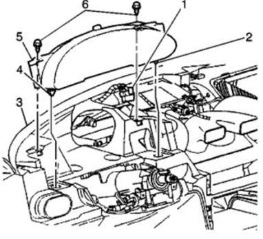
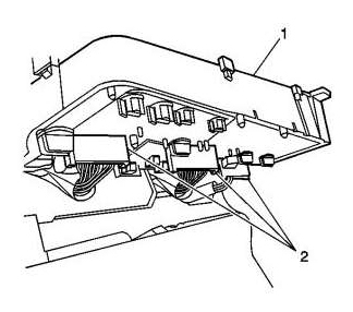
11. Remove the screws (6) from the top of the I/P
cluster (5).
12. Remove the I/P cluster (5) pulling rearward.
13. Disconnect the electrical connector (1) from the I/P cluster (5)
14. Remove the I/P cluster from the I/P.
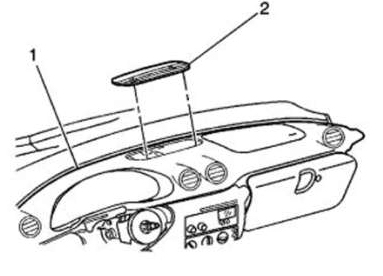
1. Release the defroster grille (2) retainers
using a small flat bladed tool.
2. Remove the grille (2) from the instrument panel (I/P) upper trim pad (1).
3. The air bag system does not need to be
disabled if it the passenger air bag is left connected during this process.
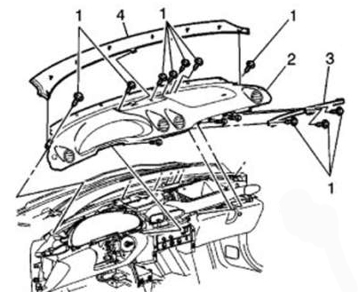
4. Remove the I/P upper trim panel (4) by lifting upward to release the
retainers.
5. Remove the screws from the I/P outer trim cover
6. Remove the I/P outer trim covers.
7. Remove the I/P accessory trim plate (3). Open
the I/P compartment door in order to access the screws (2).
8. Remove the screws (2) from the I/P accessory trim plate (3).
9. Pull the I/P trim plate (3) rearward to disengage the retainers.
10. Remove the I/P trim plate from the I/P carrier.
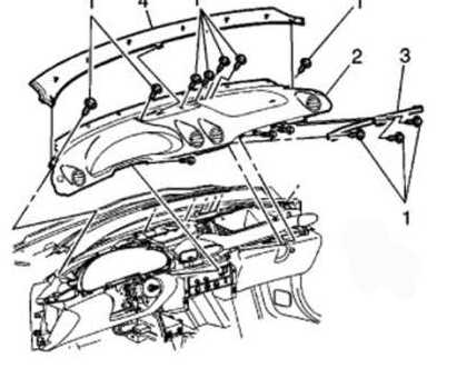
11. Remove the screws (1) from the right I/P trim
panel.
12. Remove the right I/P trim panel (3).
13. Remove the screws (1) attaching the I/P trim pad (2).
14. Remove the I/P pad (2) from the I/P carrier.
1. Disconnect negative battery cable
2. Remove passenger seat to gain room
3. Remove Left trim panel using flat-bladed plastic tool, start at top edge,
release retaining clips
4. Remove right trim panel, first removing HVAC knobs
5. Remove glove box door
6. Remove left side knee bolster. Remove 3 screws holding knee bolster to instrument panel
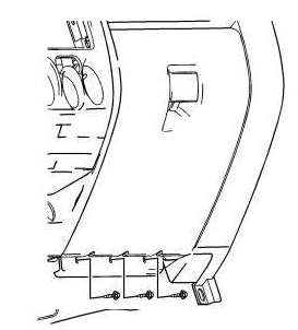
7. Unplug electrical connector (2) from headlamp switch
8. Remove right knee bolster – Remove the ashtray door and 3 upper retaining fasteners.
9. Remove the 2 left retaining fasteners.
10. Disconnect the airbag module disable switch.
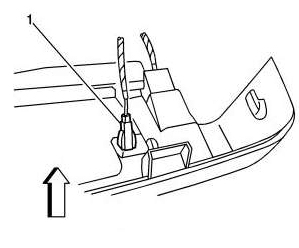
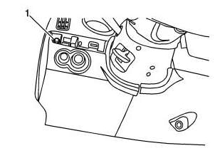
11. Disconnect the I/P compartment light
electrical connector (1).
12. Disconnect the bed cover electrical connector (2).
13. Disconnect the power point receptacle connector (1).
14. Remove bolster from vehicle.
15. Remove right airbag module. Using ¼ ratchet,
an 8 inch extension with a universal adapter and a 10mm deep well socket. Remove
2 upper airbag fasteners (1).
16. Disconnect the airbag module connector position assurance.
17. Disconnect the airbag module electrical connector.

18. Remove the 2 lower airbag retaining bolts (1)
19. Remove the airbag from the front of the I/P cluster
20. Move steering wheel to full down position
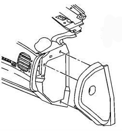
21. Remove 5 fasteners from the center trim panel
22. Release retaining clips from the center trim
panel and remove
23. Remove the instrument panel cluster seal from the IPC
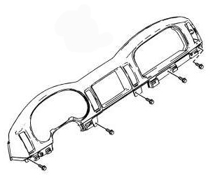
24. Remove 4 screws that retain the cluster bezel
to the I/P
25. Partially remove the cluster bezel to gain access to the electrical
connections.
26. Disconnect the electrical connections and remove cluster from dash.
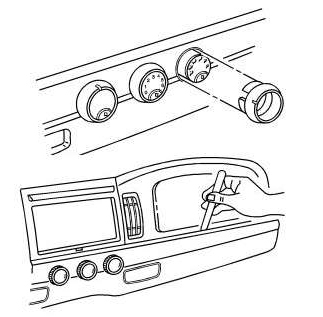
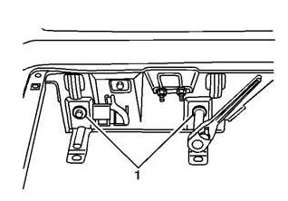
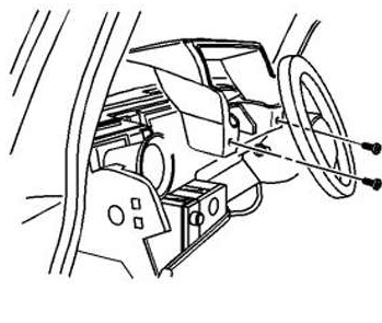
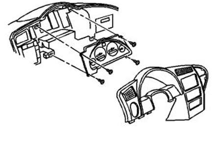
1. Remove the 4 screws which secure the plastic
trim piece that goes around the cluster and radio area
2. Gently pry the trim piece away from the dash using a flat bladed tool, use
tape on the tool if necessary to prevent damage to plastic
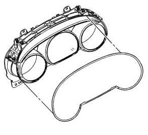
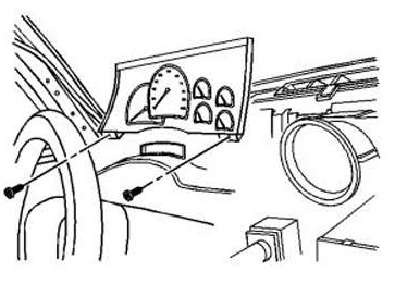
3. Remove the 4 screws (1) that hold the cluster in place.
4. Pull the cluster forward to gain access to the electrical connectors
5. Disconnect the 3 electrical connectors (2) and remove the cluster from the dash.
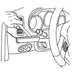
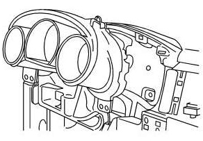
1. First, remove trim panel by removing screws that hold cluster
trim panel to instrument panel
2. Use care to remove cluster trim panel from tabs in instrument panel
3. Now, remove the screws from the instrument cluster
4. Finally, disconnect the instrument cluster electrical connection.
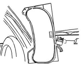
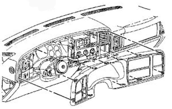
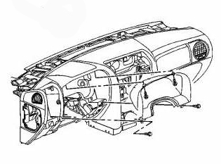
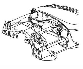
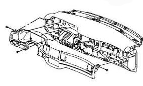
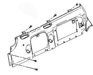
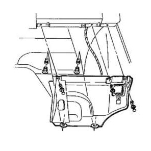
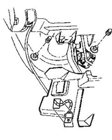
Instrument panel insulator – right side:
1. Remove the push-in retainers from the IP (instrument panel)
insulator to instrument panel.
2. Remove the press-on retainers from the IP insulator to dash mat.
3. Unsnap the IP courtesy lamp from the IP insulator
4. Remove the IP insulator from the instrument panel
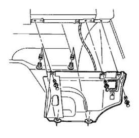
Instrument panel insulator – left side:
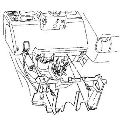
5. Remove the push-in retainers from the IP insulator to
instrument panel.
6. Remove the press-on retainers from the IP insulator to dash mat.
7. Unsnap the IP courtesy lamp from the IP insulator
8. Remove the IP insulator from the instrument panel
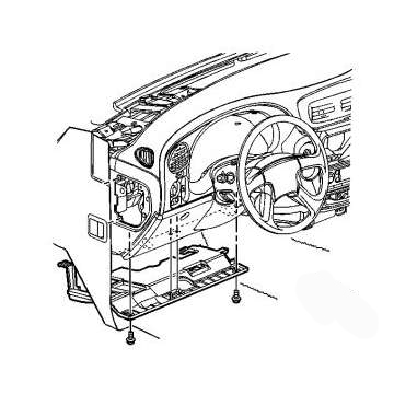
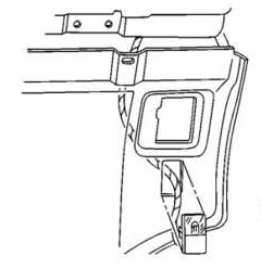
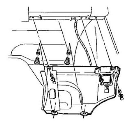
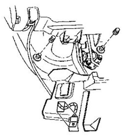
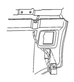
Knee Bolster
9. Remove the bolts/screws from the bottom of the knee bolster
10. Pull on the knee bolster in order to release the upper clips
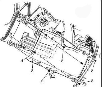
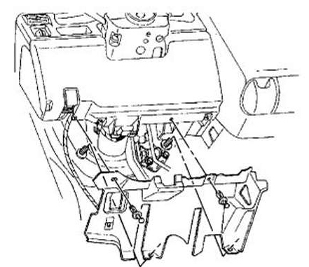
Accessory Trim Plate
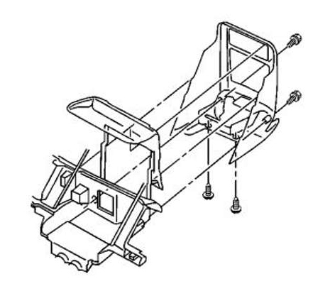
11. Open the ashtray or the cup holder.
12. Remove the following sets of screws:
- Two screws from the front of the trim panel. For access to the front screws,
remove the ashtray or the cupholder.
- Two screws from the bottom of the trim panel. For access to the bottom
screws, remove the console storage box.
13. Use a small, flat-bladed tool in order to remove the upper tabs on the IP
accessory plate from the instrument panel.
14. Disconnect the electrical connectors, if equipped.
15. Remove the IP accessory trim plate from the instrument panel.
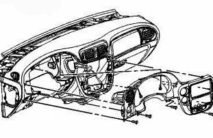
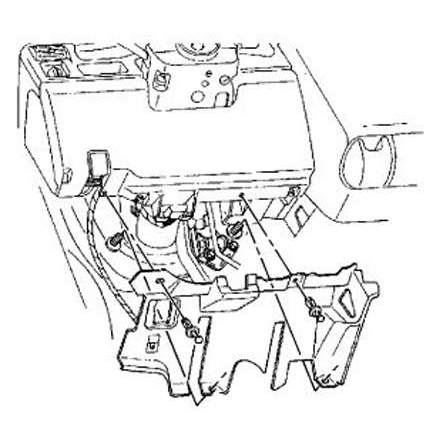
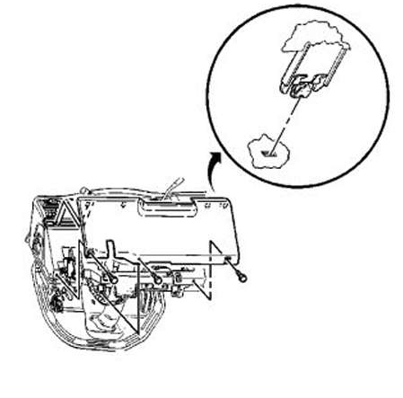
Instrument Cluster Trim Plate
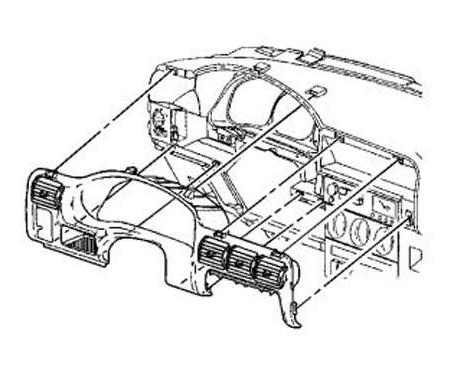
16. Position the tilt steering wheel to the lowest position.
17. Pull on the IP cluster trim plate in order to release the clips that secure
the IP
cluster trim plate to the instrument panel. Begin near the headlamp switch and
work toward the center of the vehicle IP cluster trim plate.
18. Remove the IP cluster trim plate from the instrument panel.
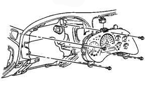
Instrument Cluster Removal – Important the ignition switch must be in the OFF position when removing the instrument panel cluster.
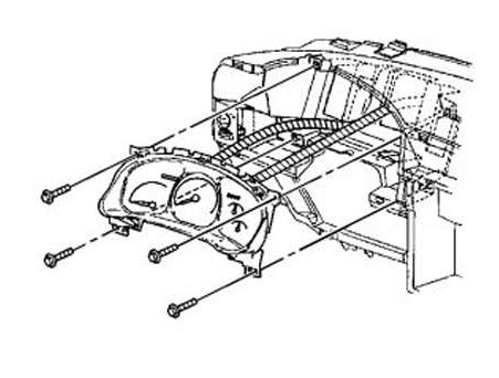
19. Remove the screws from the IP cluster to instrument panel.
20. Remove the IP cluster from the instrument panel.
Instrument panel insulator – right side:
1. Remove the push-in retainers from the IP (instrument panel)
insulator to instrument panel.
2. Remove the press-on retainers from the IP insulator to dash mat.
3. Unsnap the IP courtesy lamp from the IP insulator
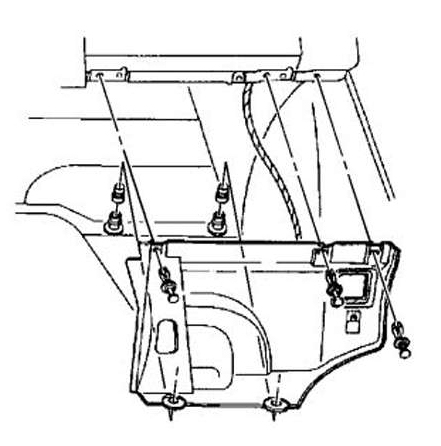
4. Remove the IP insulator from the instrument panel
Instrument panel insulator – left side:
5. Remove the push-in retainers from the IP insulator to
instrument panel.
6. Remove the press-on retainers from the IP insulator to dash mat.
7. Unsnap the IP courtesy lamp from the IP insulator
8. Remove the IP insulator from the instrument panel
Knee Bolster
9. Remove the bolts/screws from the bottom of the knee bolster
10. Pull on the knee bolster in order to release the upper clips
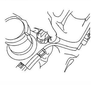
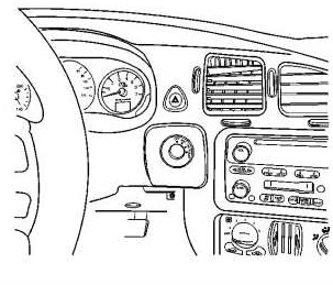
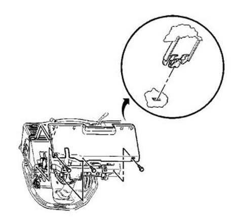
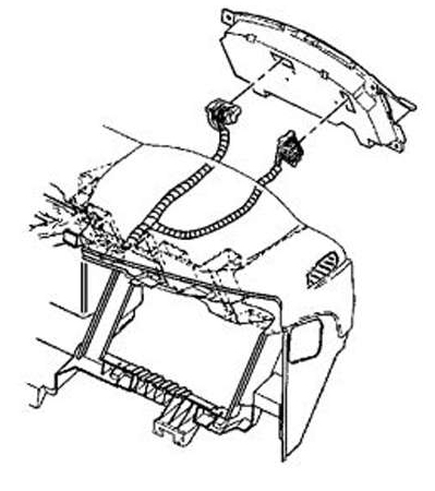
Driver Information Display Switch
11. Use a flat-bladed tool to pry the cover of the driver info center panel from the instrument panel
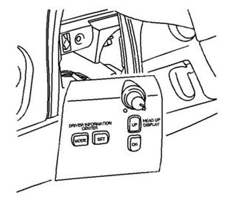
12. Disconnect the electrical connectors from the driver info center panel and remove.
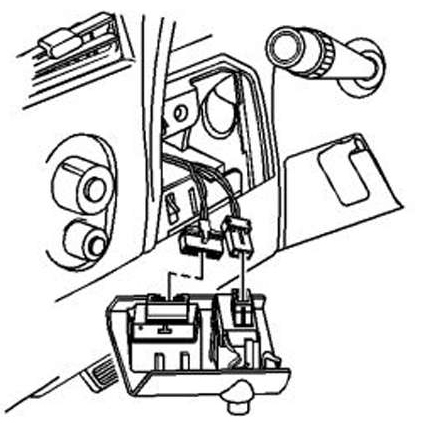
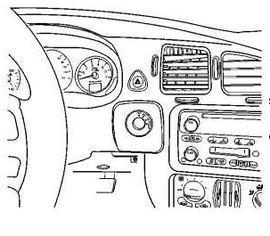
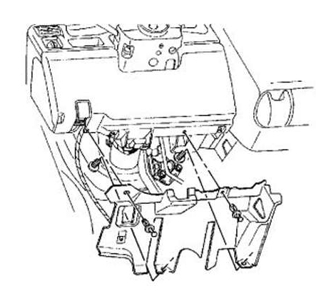
Cluster Trim Plate Bezel –
Important: turn the ignition switch to the OFF position before you remove the instrument panel cluster.
13. Loosen the steering column bracket. Lower the steering
column
14. Remove the trim plate bezel from the instrument panel cluster.
15. Remove the screws from the IP cluster.
16. Disconnect the electrical connectors from the IP cluster and remove.
Feel free to contact us with any questions @ 214-616-7858 or via email at Shannon@clusterfixer.com
3751 Main St. Suite 600, #360 * The Colony Texas 75056